


Documentation
Description
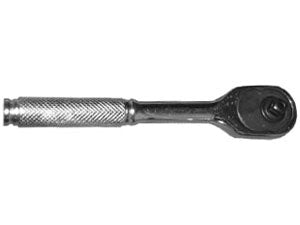
Hand Installation Tool with Minimum Edge Distance.
Ordering Information
• Determine broach hex dimensions of the pins to be installed.
• See table for (“B” and “E”) dimensions to match broached hex and required reach.
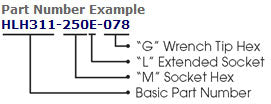
• Determine Complete Tool Assembly Part Number.
| Code | L Extended Socket |
|---|---|
| E | 0.750 |
| G | 0.875 |
| H | 1.375 |
| C | 1.500 |
| F | 1.750 |
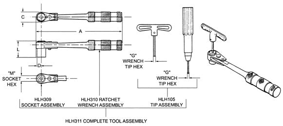
| “M” Socket Hex | “G” Wrench Tip Hex | Complete Tool Assy. Part Number |
Dimensions | Ratchet Wrench Assy. Part No. |
Socket Assembly Part No. |
Wrench Key Assembly Part No. |
|||
|---|---|---|---|---|---|---|---|---|---|
| A | L | C | D | ||||||
| 1/4” | 5/64” | HLH311-250E-078 | 6.40 | 0.750 | 0.562 | 0.281 | HLH310-1 | HLH309-250E | HLH105-078 |
| HLH311-250F-078 | 1.75 | HLH310-1 | HLH309-250F | HLH105-078 | |||||
| 5/16” | HLH311-312E-078 | 0.750 | HLH310-1 | HLH309-312E | HLH105-078 | ||||
| HLH311-312H-078 | 1.375 | HLH310-1 | HLH309-312H | HLH105-078 | |||||
| HLH311-343E-078 | 0.750 | HLH310-1 | HLH309-343E | HLH105-078 | |||||
| 11/32” | 3/32” | HLH311-343E-094 | HLH310-1 | HLH309-343E | HLH105-094 | ||||
| HLH311-343H-094 | 1.375 | HLH310-1 | HLH309-343H | HLH105-094 | |||||
| HLH311-437E-094 | 0.750 | HLH310-1 | HLH309-437E | HLH105-094 | |||||
| 7/16” | HLH311-437G-094 | 0.875 | 0.750 | 0.375 | HLH310-2 | - | HLH105-094 | ||
| HLH311-437C-094 | 1.500 | HLH310-2 | - | HLH105-094 | |||||
| HLH311-437C-094 | 1.750 | HLH310-2 | - | HLH105-094 | |||||
| 1/8” | HLH311-437E-125 | 0.750 | HLH310-2 | - | HLH105-125 | ||||
| 1/2” | 5/32” | HLH311-500G-156 | 0.875 | HLH310-2 | - | HLH105-156 | |||